10BASE-T1S for Industry: Wiring, Modular Bus Design and CAN Migration
The IEEE Ethernet & IP @ Automotive Technology Day 2026 took place on 14–15 October in Gothenburg. Several presentations focused on 10BASE-T1S. The research concerns vehicles, but some questions are equally important for industrial sensors, control cabinets, production lines and building automation.
This article selects three topics. We first report what the presenters studied, then discuss what industrial engineers can take from it. These are engineering considerations, not new installation standards.
1. Cable routing and untwist: lessons from Molex
Research. Safal Sharma and Abbas Alwishah (Molex) studied the influence of nearby unshielded twisted pairs (UTP) on 10BASE-T1S signal quality. In their model, changing the centre-to-centre spacing of adjacent pairs from 9.5 mm to 2 mm increased coupling and timing jitter. The study suggests 6.5 mm or more as a useful spacing target, with 5 mm as a lower design reference. Keeping untwist at or below 30 mm is another practical guideline. These figures refer to the studied cable geometry; 6.5 mm is not a general required clearance between outer cable jackets or between mains and data cables.
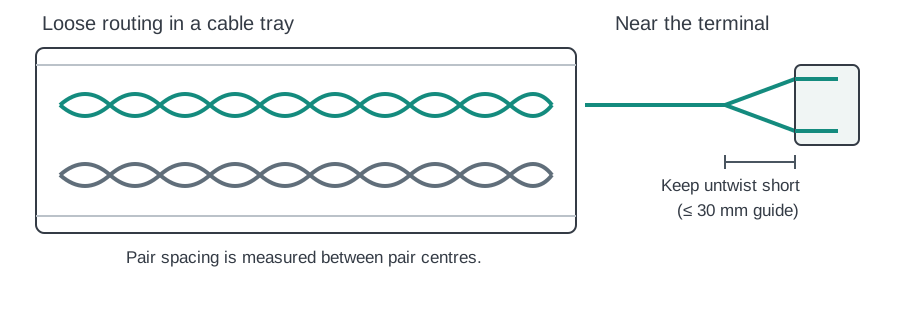
Industrial view. The centre-to-centre distance between pairs matters, not just the visible gap between cable jackets. In a control cabinet, loose routing may be preferable to tightly lacing many signal cables together over long distances. Pay attention where cables are compressed at feedthroughs and cable glands. Keep each pair twisted as close as practical to the terminal. 30 mm is a useful rule of thumb, not a sharp pass/fail limit. The study does not compare shielded and unshielded cables, and it does not establish a separation rule for 230 V power cables.
Original material: Molex presentation (PDF) · Watch the talk

2. A fixed bus with removable modules
Research. JASPAR, with authors from Mazda, Honda and Toyota, examined more flexible wiring for 10BASE-T1S. A five-node bus with 1 m branches using CAN-grade UTP cable achieved communication and met the applied eye-mask criterion in the tested setup. Signal quality was lower than in the reference topology, and further EMC work remains. The result is not a general approval of 1 m stubs.
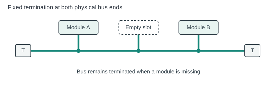
Industrial view. A bus can be designed with fixed termination at its two physical ends, independent of whether a controller is fitted at those ends. The last bus termination does not require an active node. A continuous passive backbone with short connections to module slots may help in production test systems and building automation. Modules can be inserted or exchanged without deliberately removing the end termination.
With suitable power, addressing and network management, modules may also be programmed one after another or concurrently over the Ethernet network. A module still needs power and a working connection to receive firmware. Empty slots, unpowered equipment, insertion transients and branch lengths must be checked in the real design; this was not a general hot-plug qualification.
Original material: JASPAR presentation (PDF) · Watch the talk

3. From CAN to 10BASE-T1S: what really changes?
Research. The JASPAR work explicitly addresses CAN replacement. It shows why familiar CAN-style wiring is attractive and investigates whether 10BASE-T1S can offer more freedom in bus layout. The presentation does not claim a plug-in electrical or software replacement for CAN.
Industrial view. Both CAN and 10BASE-T1S can connect multiple devices along one bus with termination at the physical ends. But migration involves more than changing transceivers:
| Question | CAN / CAN FD | 10BASE-T1S |
|---|---|---|
| Communication | CAN frames and identifiers | Ethernet frames, Ethernet addressing and higher-layer protocols |
| Media access | CAN arbitration | Ethernet half-duplex operation; PLCA can coordinate multidrop access |
| Data rate | Depends on CAN or CAN FD bit timing | 10 Mbit/s physical Ethernet rate |
| Software | CAN interfaces and CAN-based applications | Ethernet MAC/PHY, network stack and application protocol |
| Migration | Existing CAN system | Redesign of electronics, software and validation |
There may be opportunities to reuse parts of the cabling concept, but existing cables, connectors, stubs and EMC behaviour need their own qualification. CAN FD performance is not described by one universal bit rate. Neither technology is automatically better for every industrial task.
For a machine builder, the key question is whether Ethernet connectivity, protocol integration and shared infrastructure justify the migration effort.
Terms used here
- 10BASE-T1S: 10 Mbit/s Single Pair Ethernet for short-reach links, including multidrop buses.
- CAN / CAN FD: Controller Area Network and its Flexible Data-rate extension.
- UTP: Unshielded Twisted Pair — two conductors twisted together without an overall shield.
- Untwist: Length over which the two conductors are separated or no longer twisted near a connection.
- Stub: Short branch from the main bus to a node.
- Termination: Electrical end-of-line network that matches the bus; it is not necessarily inside a powered device.
- PHY: Physical-layer interface handling the electrical link.
- PLCA: Physical Layer Collision Avoidance, a coordinated access method for multidrop 10BASE-T1S.
- EMC: Electromagnetic compatibility — limiting unwanted emission and susceptibility.
Explore 10BASE-T1S with BE-IIS
BE-IIS develops industrial interface hardware for Raspberry Pi. Our 10BASE-T1S HAT++ makes it possible to build and evaluate Ethernet multidrop systems. For existing bus equipment, the CAN FD HAT++ provides a complementary interface. See also our 10BASE-T1S performance test and the full product catalogue.
This article is an independent industrial interpretation of publicly available presentations. Original research and figures belong to their respective authors. The simplified diagrams on this page are original BE-IIS illustrations and are not copied conference slides.