Using BE-IIS HAT++ T1L/T1S as a Transparent Media Converter
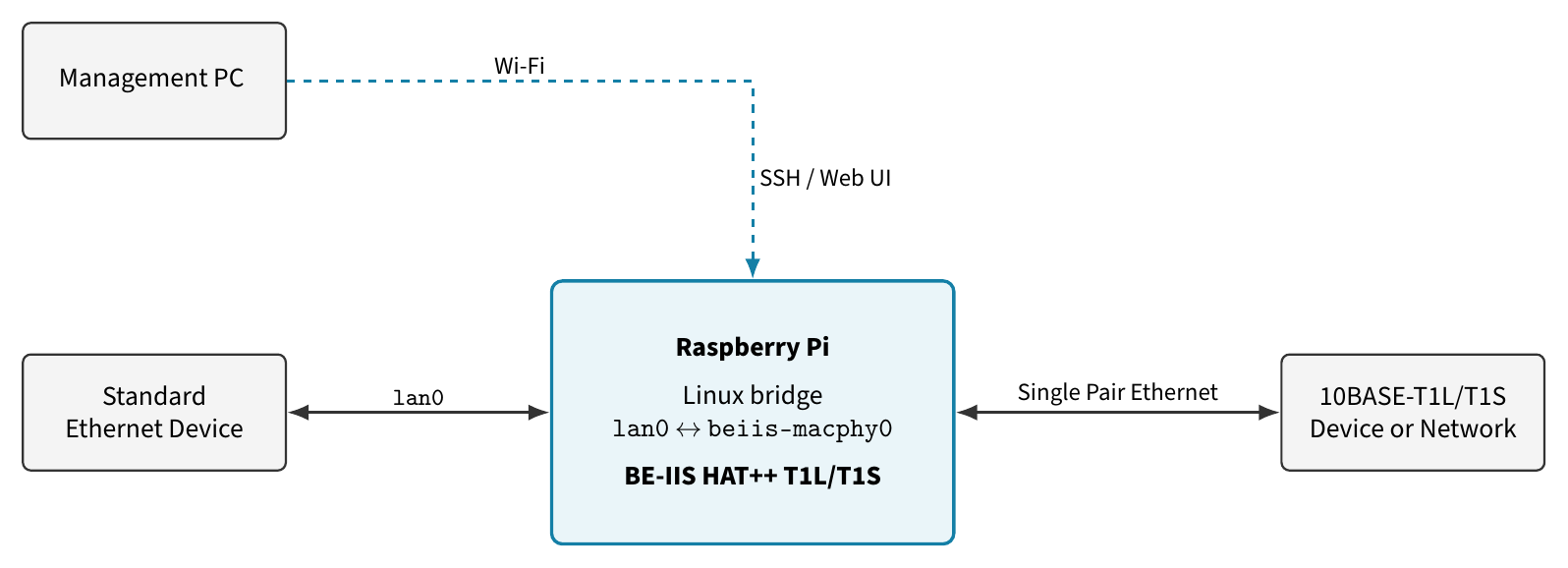
A Raspberry Pi with a BE-IIS HAT++ T1L or T1S board forms a transparent connection between standard Ethernet and Single Pair Ethernet.
In the basic setup, it works as a pure Layer-2 media converter. Ethernet frames pass unchanged between the LAN port and the 10BASE-T1L or 10BASE-T1S interface. The converter does not route traffic, use NAT or translate application protocols.
Unlike a fixed-function media converter, this system remains open and configurable. The Raspberry Pi adds an independent Wi-Fi management interface, SSH access, a web interface, packet capture, interface statistics and system logs. For 10BASE-T1S, PLCA can be configured directly on the same device.
The system can be used as:
- A transparent LAN-to-T1L or LAN-to-T1S media converter
- A remotely managed converter with Wi-Fi, SSH and web configuration
- A diagnostic device with packet capture and traffic statistics
- A PLCA coordinator or PLCA node
- A multi-port Linux bridge or software switch
- A base for MQTT, logging or protocol gateway applications
With an additional BE-IIS HAT++ PoSPE board, data and power can share the same single pair. Further HAT++ boards can add LAN, T1L, T1S, CAN, Modbus or UART interfaces without replacing the platform.
System Architecture
The wired interfaces are joined by a Linux bridge:
LAN device
    |
   eth0
    |
  br-spe
    |
beiis-t1s0 or beiis-t1l0
    |
BE-IIS HAT++ T1S or T1L
    |
10BASE-T1S network or 10BASE-T1L link
Wi-Fi stays separate and provides SSH and web access.
The converter has no IP address on the data path:
| Interface | Function | IP address |
|---|---|---|
wlan0 |
Management | DHCP or static |
eth0 |
LAN bridge port | None |
beiis-t1s0 / beiis-t1l0 |
SPE bridge port | None |
br-spe |
Layer-2 bridge | None |
Only the end devices need IP addresses. Frames pass through without routing, NAT or protocol conversion.
Hardware
- Raspberry Pi with Ethernet and Wi-Fi
- BE-IIS HAT++ T1S or T1L
- Standard Ethernet cable
- Suitable Single Pair Ethernet cable
- A second T1S/T1L device or network
For 10BASE-T1S, use the correct bus topology, termination and PLCA settings.
1. Install BE-IIS Hardware Support
The BE-IIS Installer installs the required drivers, Device Tree overlays, udev rules and system integration.
$ sudo apt update
$ sudo apt install -y git

$ cd ~
$ git clone https://github.com/be-iis/be-iis-installer.git
$ cd be-iis-installer/scripts/install
$ sudo ./install-all.sh
$ sudo reboot
Reconnect over Wi-Fi and check the interfaces:
$ ip -br link

wlan0          UP
eth0           DOWN
beiis-t1s0     DOWN
For a T1L setup, the SPE interface is the corresponding T1L interface.
2. Install BE-IIS Network Web
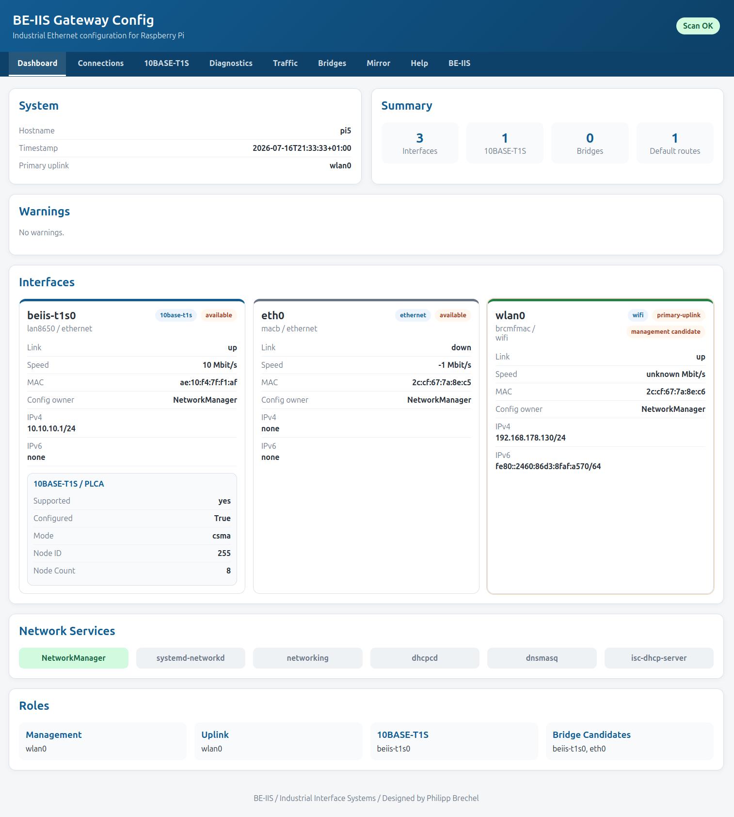
BE-IIS Network Web provides browser-based configuration for connections, bridges, PLCA, diagnostics, mirror ports and packet capture.
$ cd ~
$ git clone https://github.com/be-iis/be-iis-network-web.git
$ cd be-iis-network-web
$ chmod +x install_be_iis_network_web.sh
$ sudo ./install_be_iis_network_web.sh
Check the service and find the Wi-Fi address:
$ systemctl status be-iis-network-web
$ hostname -I

192.168.178.50
Open:
http://192.168.178.50:8080/
3. Remove Existing IP Profiles
An existing LAN or SPE profile may still assign an IP address. Deactivate and delete that profile before adding the interface to the bridge.
Keep the Wi-Fi connection active.
In Connections:
- Deactivate the old
eth0profile. - Deactivate the old
beiis-t1s0orbeiis-t1l0profile. - Delete the inactive profiles.
- Do not remove the Wi-Fi profile.
4. Create the Transparent Bridge
Open Bridges and create:
| Setting | Value |
|---|---|
| Bridge | br-spe |
| IPv4 | Disabled |
| IPv6 | Ignore or disabled |
| STP | Disabled |
| Autoconnect | Enabled |
Add both ports:
| Port profile | Interface | Bridge |
|---|---|---|
br-spe-port-eth0 |
eth0 |
br-spe |
br-spe-port-beiis-t1s0 |
beiis-t1s0 |
br-spe |
For T1L, add the T1L interface instead.
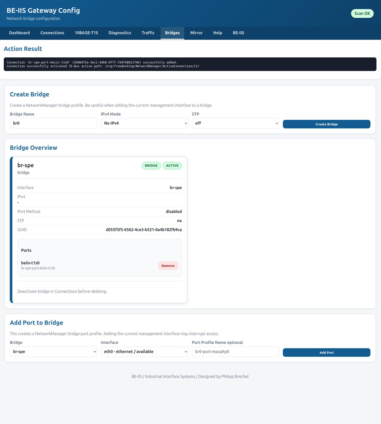
NetworkManager stores the profiles and restores the converter after every boot.
Verify the result:
$ nmcli connection show --active
$ bridge link
$ ip -br address
Expected active profiles:
Wi-Fi management profile
br-spe
br-spe-port-eth0
br-spe-port-beiis-t1s0
eth0, the SPE interface and br-spe must not show an inet address.
5. Configure 10BASE-T1S PLCA
This step is only required for T1S.
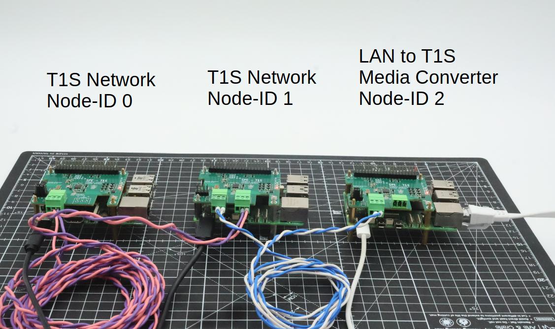
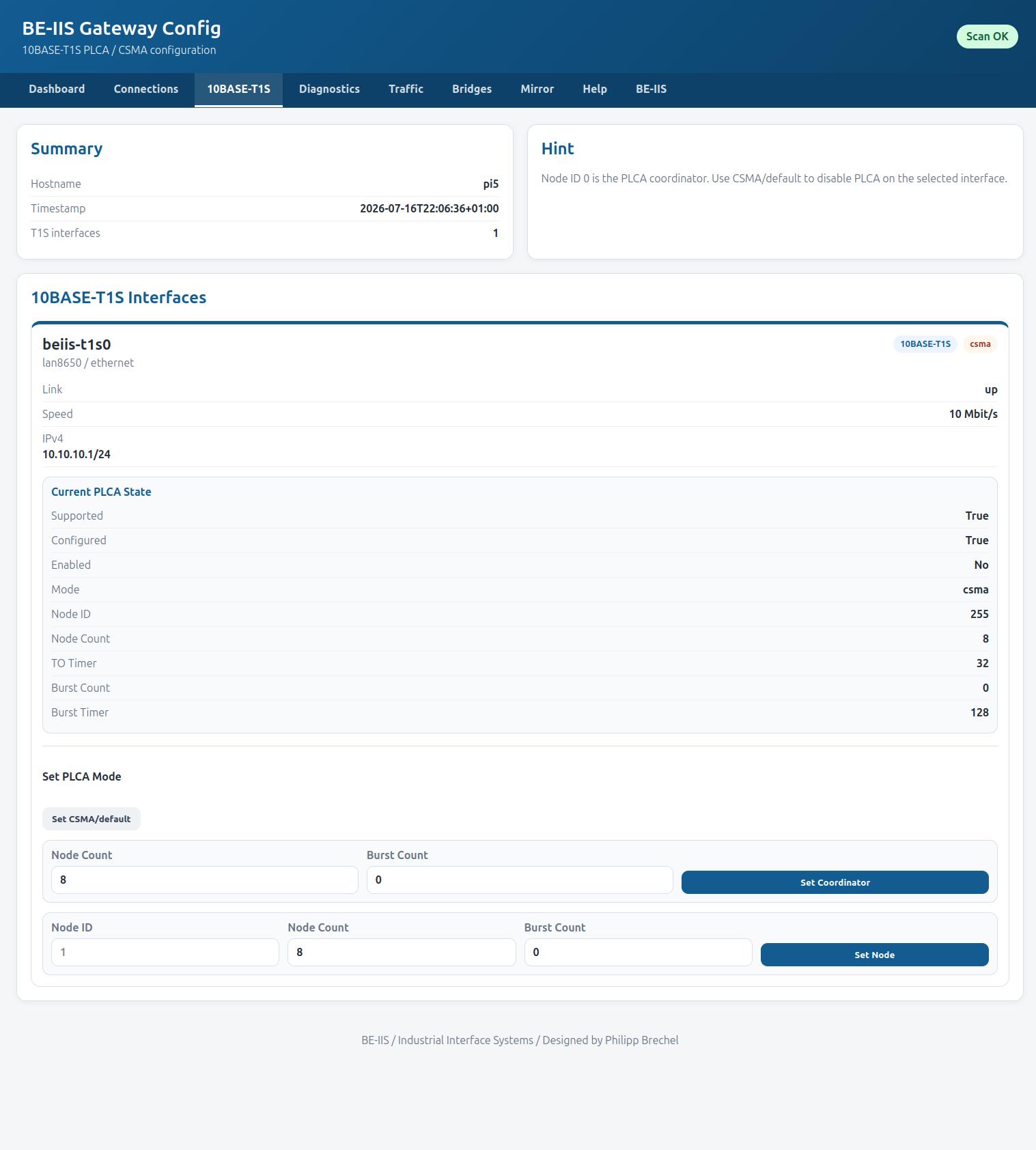
Open 10BASE-T1S and select CSMA, PLCA coordinator or PLCA node. A PLCA network uses one coordinator with Node ID 0. Each other node needs a unique ID.
Example test network:
| Device | PLCA role |
|---|---|
| T1S node 1 | Coordinator, Node ID 0 |
| T1S node 2 | Node ID 1 |
| Media converter | Node ID 2 |
10BASE-T1L is point-to-point and does not use PLCA.
6. Test the Data Path
Start an iperf3 server on the remote device:
$ iperf3 -s
Send a 9 Mbit/s UDP stream from the LAN-connected PC:
$ iperf3 -c <device-ip> \
    -u \
    -b 9M \
    -t 30 \
    -i 1 \
    -l 1400
The test setup passed 9 Mbit/s UDP traffic through:
PC -> LAN -> Raspberry Pi bridge -> BE-IIS HAT++ T1S -> T1S network -> device
The Raspberry Pi did not route the packets. It forwarded Ethernet frames between both media.
Diagnostics
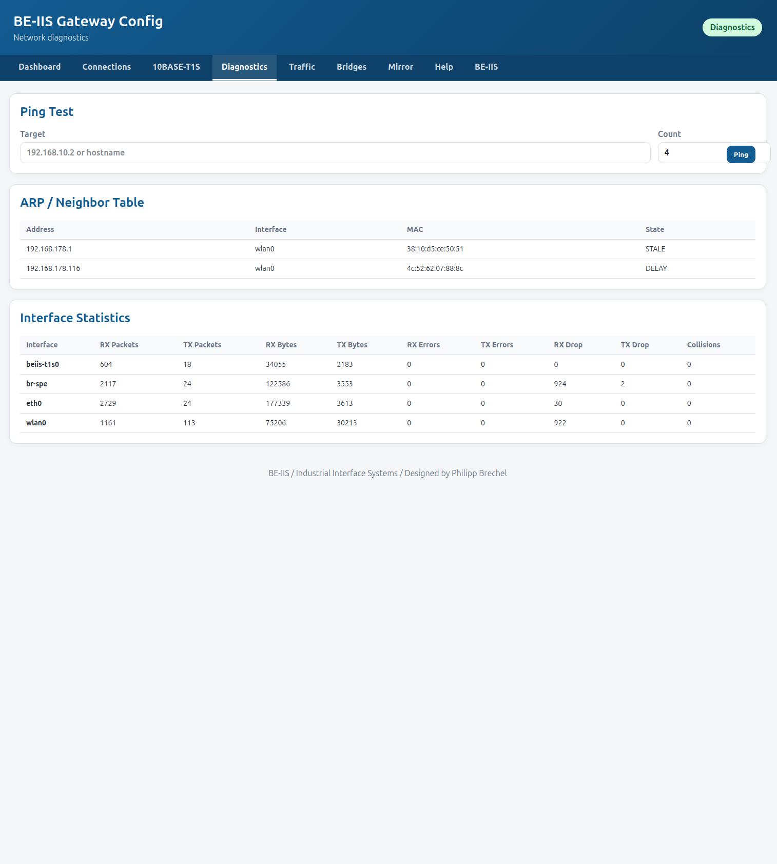
The converter can inspect the same traffic it forwards.
$ sudo tcpdump -ni beiis-t1s0
$ ip -s link show beiis-t1s0
$ ethtool -S beiis-t1s0
BE-IIS Network Web also provides ping, neighbor tables, packet capture, protocol analysis, traffic flows and mirror-port configuration.
Optional Power over Single Pair Ethernet
A BE-IIS HAT++ PoSPE board can add power to the same pair used for T1L or T1S data.
This can reduce a remote node to one cable for:
- Communication
- Power
- Diagnostics
Check the source and sink configuration, input voltage, cable loss and power budget before enabling PoSPE.
Why Use a Raspberry Pi?
A fixed media converter only changes the physical interface. The Raspberry Pi adds:
- Wi-Fi management without touching the data path
- Persistent startup configuration with NetworkManager
- SSH, web configuration and system logs
tcpdump,tshark,ethtooland bridge diagnostics- PLCA configuration for T1S
- Mirror ports and traffic analysis
- Additional LAN, T1L, T1S, CAN, Modbus or UART HAT++ boards
- Custom services such as MQTT, logging or protocol gateways
- A path from two-port converter to multi-port software switch
The hardware can start as a transparent media converter and grow with the application.